

Separation of solids from water and other liquids is required in various industrial processes. Suspended solids can be easily separated by filtration, decantation and various other methods. However, separation of dissolved solids from water and other liquids require energy intensive methods. Generally, commercial methods used for separation of dissolved solids from water and other liquids can be separated into membrane-based methods and thermal methods.
Membrane-based methods are based on reverse osmosis principle and require a semi-permeable membrane to separate pure liquid and liquid containing dissolved solids. Under normal circumstances, pure liquid from side with pure water moves towards the liquid containing dissolved solids side because of osmosis. However, when the liquid containing dissolved solids is pressurized to pressures exceeding the osmotic pressure, the pure liquid from the liquid containing dissolved solids moves through the semi-permeable membrane towards the pure water side leaving concentrated solution on the side with liquid containing dissolved solids. This process is known as reverse osmosis. As the concentration of liquid containing dissolved solids increases, the osmotic pressure also increases thus requiring higher pressures to push pure water from the side with liquid containing dissolved solids through semi-permeable membrane to the side with pure water. For separation of sea water which contains 3% NaCl by weight using reverse osmosis method, the osmotic pressure reaches very high value for saline water with 6%-7% NaCl by weight making it not possible practically to separate beyond 6%-7% concentration by weight of NaCl in the saline water. This concentrated saline water poses environmental problems when disposed-off in rivers or lakes or in sea. Also, costly pretreatment of liquid to be separated is required before applying reverse osmosis methods to avoid fouling of semi-permeable membrane.
Thermal methods like distillation, freezing and gas hydrate-based water treatment can be used to separate pure water or pure liquid from saline water or from liquid containing dissolved solids. Of these, only distillation-based systems are in use commercially with freezing-based systems found to be techno-commercially non-viable and gas hydrate-based water treatment systems not been tested extensively. Various modifications have been proposed in distillation-based systems to decrease operating cost while retaining the simplicity of the system. However, it has been found to be not possible practically or very expensive both operationally and infrastructure-wise to use various modifications of distillation-based systems like mechanical vapor recompression (MVR) and multiple effect distillation (MED) to desalinate water or separate pure liquid from liquid containing dissolved solids till complete crystallization of dissolved solids.
Therefore, there exists a requirement of a modification of distillation-based system to separate pure liquid from liquid containing dissolved solids till complete crystallization of dissolved solids which is less expensive both operationally and infrastructure-wise and simple to implement.
A new distillation-based water desalination technology to separate pure water from water containing any concentration of dissolved solids till complete crystallization of dissolved solids is proposed which is less expensive both operationally and infrastructure-wise and extremely simple to implement. The technology relates to more efficient and more operationally flexible form of distillation and is based on a new concept given by the inventor.
As per the concept which relates to simultaneous evaporation and condensation in connected vessels, the molar rate of evaporation in evaporation vessel, molar rate of transfer of vapors from evaporation vessel to condensation vessel through a connected pipe and molar rate of condensation in condensation vessel for an isolated system with no heat or mass exchange with atmosphere at a given instance of time will always be same. Any change in temperature or pressure of evaporation or condensation vessel will result in automatic change in the temperature and pressure of the other vessel so as to maintain equal rate of evaporation, transfer and condensation but at a different rate from the rate before the change. The concept can be extended to a distillation system wherein molar rate of transfer of vapors from evaporation to condensation vessel is increased by compression or other means.
The technology can remove dissolved solids from water with any concentration of dissolved solids till complete crystallization. The proposed technology uses very simple and inexpensive components resulting in very low capital cost and can desalinate water of any salinity till complete salt crystallization at low energy consumption. The technology can use any waste hot or cold stream to desalinate water or a standalone system not requiring any waste hot or cold stream can be designed as per the technology.

FIGURE 1
The invention consists of an evaporation vessel and a condensation vessel with their vapor spaces connected by a connecting pipe. The evaporation vessel and the condensation vessel have internal or external heat transfer coils to heat and cool the evaporation vessel and condensation vessel respectively. A water inlet pump is configured in the evaporation vessel to pump in saline water. An air outlet with an air outlet valve is configured on top of the condensation vessel to remove non-condensable gases or air from the system. A salt/ concentration saline outlet with a valve is configured on the bottom of the evaporation vessel to remove salt/ concentrated saline water out of the evaporation vessel. A water outlet pump is configured on the bottom of condensation vessel to pump out desalinated water. Optionally, a steam inlet with a valve is configured on top of the evaporation vessel to pressurize the system with steam and push the crystallized salt/ concentrated saline water out from the bottom of evaporation vessel and push the desalinated water out from the bottom of the condensation vessel through a desalinated water outlet with a configured valve. The complete system is made airtight and thermally insulated so as to have no mass or heat exchange with the surroundings.
The initial pressure configuration during start-up of the system is attained by filling both the vessels completely with saline water till all non-condensable gases or air is removed from air outlet and saline water starts overflowing through it. Subsequently, the saline water from the condensation vessel is completely removed using water outlet pump. This will result in evaporation of water from saline water at low pressure so as to fill the condensation vessel with water vapors which are in vapor liquid equilibrium with saline water in the evaporation vessel. Finally, the evaporation vessel will be filled with saline water at a temperature close to its initial temperature whereas condensation vessel will be filled with water vapors at the final temperature of saline water and at a pressure equal to the vapor liquid equilibrium pressure of saline water corresponding to the final temperature of saline water.
Alternatively, the system is pressurized with steam which is either produced in the evaporation vessel or introduced in the evaporation vessel through steam inlet. Further, non-condensable gases and air along with steam are removed from the system through air outlet till the concentration of non-condensable gases and air in outlet becomes very less or concentration of steam in outlet becomes very high. Subsequently, air outlet valve is closed and saline water is pumped in the evaporation vessel through water inlet pump. Saline water present in evaporation vessel and steam present in evaporation vessel and condensation vessel exchange heat and the final temperature of the system will be close to the initial temperature of saline water whereas the final pressure of the system will be the vapor liquid equilibrium pressure of the saline water corresponding to the final temperature of the system.
Evaporation of water from evaporation vessel is started by pumping hot heat transfer fluid through the heat transfer coil of evaporation vessel. Condensation of water in condensation vessel is started by pumping cold heat transfer fluid through the heat transfer coil of condensation vessel. Any fluid like water, glycol, oil, steam or gases can be used as heat transfer fluid for heat transfer coils of evaporation vessel and condensation vessel. Apart from pumping hot and cold heat transfer fluid through heat transfer coils, any other conductive, convective or radiative means of heating like electric coils or solar concentrators and any other conductive, convective or radiative means of cooling like fans or water wetting/ ice covering of surfaces can be used for evaporation of water in evaporation vessel and condensation of water in condensation vessel respectively. Rate of evaporation and condensation can be controlled by changing the temperature and pressure of the evaporation vessel by changing the temperature or flowrate of hot heat transfer fluid, by changing the temperature and pressure of condensation vessel by changing the temperature or flowrate of cold heat transfer fluid or by changing the vapor flowrate through the connecting pipe by varying the opening of the vapor transfer valve configured in the connecting pipe.
Water inlet pump and water outlet pump are operated continuously or intermittently to pump in saline water to evaporation vessel and pump out desalinated water from condensation vessel. After substantial amount of salt is collected in the evaporation vessel or after desired salinity of concentrated saline water is attained in the evaporation vessel, the system is stopped and opened to atmosphere to remove crystallized salt/ concentrated saline water from the evaporation vessel and desalinated water from condensation vessel. Again, the pressure initialization of the system is done and the same cycle of evaporation and condensation is repeated till substantial amount of salt is collected or desired salinity of concentrated saline water is attained in the evaporation vessel. Heating of evaporation vessel and cooling of condensation vessel could be done continuously using constant or varying temperatures and flowrates of hot and cold heat transfer fluids or intermittently by starting and stopping flow of hot and cold heat transfer fluids. Any waste hot or cold fluid stream available from some other process could be used as hot or cold heat transfer fluid in evaporation vessel or condensation vessel whereas water at ambient temperature could be used as cooling or heating liquid in the condensation vessel or evaporation vessel respectively.

FIGURE 2
Heating of evaporation vessel and cooling of condensation vessel can be accomplished using a single refrigeration system. The evaporation side of the refrigeration system can be used to cool the condensation vessel whereas the waste heat of the refrigeration system can be used to heat the evaporation vessel. As the waste heat released by the refrigeration system is more than the heat absorbed on the cooling/ evaporation side of the refrigeration system (around 1.5 times) and as the rate of evaporation and condensation in the invention is always same requiring and releasing nearly same heat so excess waste heat is always available in the refrigeration system. This excess waste heat is released to the atmosphere using an air cooled or water-cooled condenser. This kind of system is an efficient stand-alone system not requiring any waste hot or cold fluid stream or any external heating of evaporation vessel or cooling of condensation vessel using any conductive, convective or radiative means.

FIGURE 3
The rate of evaporation and condensation can be increased by increasing the vapor flowrate through the connecting pipe by opening of the vapor transfer valve configured in the connecting pipe. The rate of evaporation and condensation can be increased by using a connecting pipe of larger area and operating the system with fully open vapor transfer valve. However, connecting pipe of very large area and a very large vapor transfer valve are not desirable because of high increase in infrastructure cost and very less increase in rate of evaporation and condensation with area of connecting pipe beyond a large area. A compressor can be configured in the connecting pipe to further increase the vapor flowrate through the connecting pipe resulting in further increase in rate of evaporation and condensation. A bypass pipe can be configured between the evaporation vessel and condensation vessel parallel to the connecting pipe to facilitate pressure initialization during start-up of the process. The compressor is isolated by closing the inlet and outlet of compressor in the connecting pipe and bypass valve configured in the bypass pipe is opened for pressure initialization during start-up whereas the inlet and outlet of compressor is opened and bypass valve is closed during normal operation of the system.
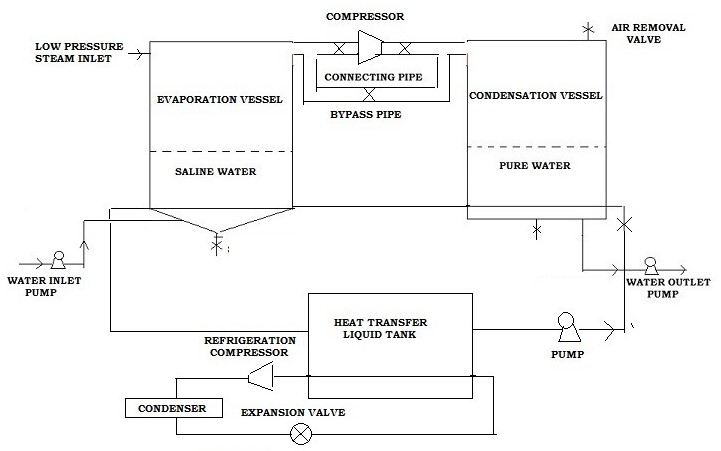
FIGURE 4
When a compressor is configured in the connecting pipe, the pressure of condensation vessel and corresponding equilibrium temperature of desalinated water in condensation vessel exceeds the pressure of evaporation vessel and corresponding equilibrium temperature of saline water in evaporation vessel. Unlike the case when no compressor is configured in the connecting pipe, in such a case, evaporation of water in evaporation vessel takes place at a lower temperature and pressure as compared to condensation of water in condensation vessel. Therefore, a single stream of heat transfer fluid at an initial temperature can initially flow through the heat transfer coils of one vessel getting heated or cooled and then through the other vessel getting cooled or heated to nearly its initial temperature. The initial temperature of this single stream of heat transfer fluid can be taken as ambient temperature avoiding any energy consumption in heating or cooling of this stream. The storage tank of the heat transfer fluid can be made suitably large in size and kept under ambient conditions to take care of slight variation in the initial temperature of the single stream of heat transfer fluid after it comes out of the other vessel.
Apart from separation of pure water from water containing dissolved solids, the technology can also be used to separate miscible liquids. Pressure initialization is performed using similar methods as used for separation of pure water from water containing dissolved solids given earlier in the article. Liquid mixture is pumped in to the evaporation vessel and evaporated whereas the evaporated vapors are condensed in the condensation vessel and pumped out of condensation vessel till the desired composition is reached in the evaporation vessel. Subsequently, liquid residue from evaporation vessel and liquid distillate from condensation vessel is removed by opening the bottom valves of the evaporation vessel and condensation vessel, pressure initialization is again performed and the separation process is repeated.
Energy details of the technology
Various configurations of the technology have been simulated using MS Excel and VBA in the process of development of the technology and can be used to find the energy consumption and optimize the configurations.
When a waste hot or cold stream is used in the system configuration where no compressor is configured in the connecting pipe, the only energy consumption of the system is the pumping energy of ambient water being pumped through heat transfer coil of condensation vessel or evaporation vessel.
When a refrigeration system is used to cool the condensation vessel and the waste heat of the refrigeration system is used to heat the evaporation vessel, the tentative energy consumption of the system with 8 m3 of NaCl brine/ day capacity till complete salt crystallization is around 300 KJ/ litre of desalinated water (= 0.08 kwh/ litre of desalinated water).
When a compressor is configured in the connecting pipe and a single stream of water at ambient temperature of 313 K is pumped successively through both the vessels, the tentative energy consumption of the system with 8 m3 of NaCl brine/ day capacity till complete salt crystallization is around 150 KJ/ litre of desalinated water (= 0.04 kwh/ litre of desalinated water).
Status of the technology
Various configurations of the technology have been computer simulated using MS Excel and VBA. The technology has been patented in USA with a patent number 10876772, in UK with a patent number GB2555951 and in India with a patent number 328525. A UK patent application number GB2019685.3 is pending for the technology. Companies interested in licensing the technology are being sought.